Part IV of building a Modern Data Platform in Azure using Terraform
Through a series of posts, we will go from nothing more than a machine that meets the minimum requirements for the azure-terraform-bootstrap to a fully functioning Enterprise-class Modern Data Platform. Our last blog post we walk through the overall architecture. In this post, we will walk through the 1.0.0 release of the terraform code that starts to build out the target state architecture of our Modern Data Platform in Azure.
Conceptual Architecture v1.0.0 Diagram
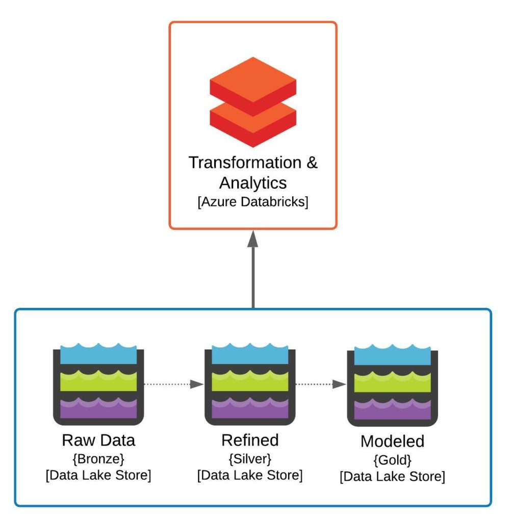
Conceptually we are building two pieces of the target state architecture discussed in our previous post. We are looking to build out the Azure Databricks instance, which will be used for data engineering as well as data discovery, investigation, analytics, and potentially even basic reporting. We are also looking to build out our core storage components, which will consist of three Azure Storage accounts, one for each of the Bronze, Silver, and Gold data stores typical in a Data Lakehouse environment. If you look through the code or the actual objects generated by the Terraform, you will discover a much more complex set of resources created in Azure. The reason for this is, as to be expected, the logical model doesn’t ever really match up to the physical solution. We are looking to create an Enterprise-class solution which in this case means added security.
Physical Architecture v1.0.0 Diagram
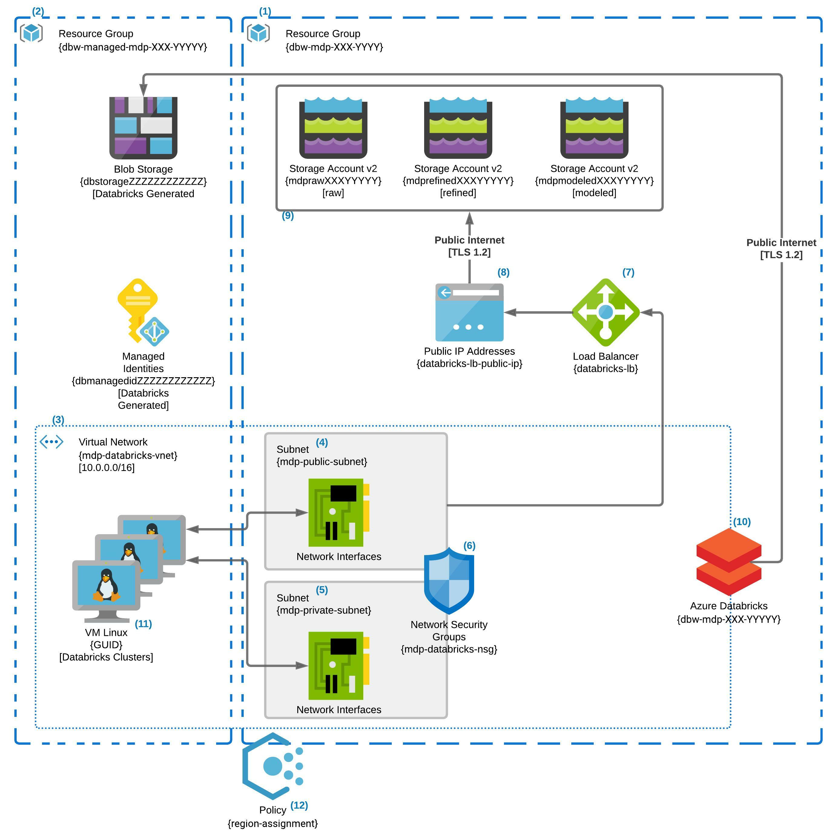
The above diagram is a much more accurate picture of what the final result of the Terraform execution will produce. Overall, we are looking to encapsulate our solution into a virtual private IP space as much as possible and restrict the rest to only communicating with a specific allowed list of IP ranges. As mentioned above, in this first release, we secure the Databricks component by disallowing direct external IP connection to the Databricks clusters. Over time we will add additional layers of protections to the Azure Storage as well as other components. We also introduce the concept of Azure Policy as an enforcement mechanism of our desired secure state. In this release, we have an Azure Policy that restricts us to using a Geopolitical zone we feel is compatible with most of our use cases.
Diagram Details
Naming Conventions – The names in the diagram have XXX or YYYYY or ZZZZZZZZZZZZ. These repeating capital letter patterns indicate three different reused strings by the terraform code to create multiple instances without naming collision concerns. XXX represents the three-letter company code expected by the terraform code. The five letter length YYYYY represents a random string generated by the terraform code at runtime and stored in the state file to be reused by any future updates. The 12 letter length Z pattern is a randomly generated string by Databricks when it creates its own managed resources.
(1) – The “dbw-mdp-XXX-YYYYY” is the core resource group for the modern data platform; it contains all of the resources created by the terraform script. Currently, the resource group contains the Azure Databricks service, the Vnet, subnets, and the load balancer and storage accounts. Lastly, it contains an NSG that secures the subnets in which virtual NICs will be placed when Databricks Clusters are spun up.
(2) – The managed resources group is automatically created by the instantiation of the Azure Databricks Service. This resource group is populated with a managed identity for the ADB services as well as a storage account for its internal functions. This resource group is where the compute instances will be spun up for any Azure Databricks Clustered associated with the ADB Service.
(3) – The mdp-databricks-vnet is a 10.0.0.0/16 sized private virtual network. The Vnet has two subnets, mdp-public-subnet and mdp-private-subnet each a /24. The remaining IP address space is unused as of now. While the Vnet is used by resources both in the core and managed resource group, it exists in the core “dbw-mpd-XXX-YYYYY” resource group.
(4) – The “Public” subnet allows egress traffic out of the Vnet to the internet via the load balancer. When Databricks clusters are spun up via the control plane, each machine will get a Virtual Nic created in this subnet. The private IP CIDR range is 10.0.1.0/24 allowing for 255 IPs resulting in 250 usable IP addresses in the subnet. Both the Public and Private subnets rely on the same NSG for network security rules and traffic control.
(5) – The “Private” subnet does not allow egress traffic out to the internet but will allow traffic with other parts of the Vnet. When Databricks clusters are spun up via the control plane, each machine will get a Virtual Nic created in this subnet. The private IP CIDR range is 10.0.2.0/24 allowing for 255 IPs resulting in 250 usable IP addresses in the subnet. Both the Public and Private subnets rely on the same NSG for network security rules and traffic control.
(6) – The mdp-databricks-nsg that protects both the public & private subnets. It allows for traffic within the Vnet as well as outbound traffic to the internet from both subnets. It also allows inbound traffic into both subnets from the Load Balancer, but only the public subnet is connected as a backend pool from the Load Balancer. Lastly, the NSG does not allow for inbound traffic from the internet into the Vnet in general.
(7) – The Load Balancer that connects the Public IP address to the Public Subnet.
(8) – Once again not much to say here its the Public IP address for the Load Balancer.
(9) – Three Azure v2 Storage Accounts to be used by Azure Data Bricks as part of the Modern Data Platform. As mentioned previously, these are to be used in the standard Bronze, Silver, Gold configuration. This means that the Raw data will be loaded to the Bronze storage account, and as it is refined in fit, form, and function, it will progress from Silver to the Gold storage account.
(10) – The Azure Databricks Service Instance is connected to the mdp-databricks-vnet. Public Access is still allowed to the workspace, but the Databricks clusters spun up by this service will be in the Vnet created as part of the terraform code. There is no public IPs to the cluster VMs will be created when they are spun up. All traffic from the Cluster VMs will be controlled by the NSG connected to both the public and private subnets.
(11) – When Azure Databricks creates clusters, the Virtual Machines will end up in the managed resource group and their NICs connected to both the private and public subnets of the mdp-databricks-vnet. Based on the current size of the public and private subnets, we can create a total of 250 VMs across any number of Databricks Clusters.
(12) – This is an Azure Policy restricting resources to the East US 2 and Central US Azure Regions. The Policy is connected to the core resource group only. You cannot add policies to the managed resource group created by the Azure Databricks platform.
One More thing before you go
Hopefully, it was explained a little better in this blog post than in the summary I gave on Github. Speaking of Github, if you want the code it is available in Github, see the “terraform-modern-data-platform v1.0.0“, below in the Useful Links section to go to the specific tag discussed in this post.
There is a little bit more included in the repository. The Terraform code will upload a CSV to the Raw storage area under a container named “example.” The Terraform then spins up a small cluster that maps the Raw storage container to the cluster mount point. Finally, the Terraform loads a Juypter notebook to the Shared Folder in the Data Bricks workspace. This notebook runs a few very simple python commands over the CSV file, just to help you make sure everything is functioning as designed and provide a beginner example of how these resources could be used. The upload of the Juypter notebook did not work as intended, but you can run your checks in a Juypter notebook:
df = spark.read.option("header", "true").csv("/mnt/example/example.csv")
df.show()